Data with Bert logo

Creating a Pulsing Conducting Baton - Part 1

Train Wreck

The last time I watched a high school band nearly fall apart mid-performance was when the relatively new, certainly nervous band director started the piece off much faster than what the students could play.

I felt bad for the students, the director, and the audience. I cringed watching it, and I sat there silently hoping that the group could keep control of the piece until finally barreling through to the end. As they did, I could feel the audience let out a sigh of relief as we applauded for not witnessing a complete train wreck.

This experience sparked the idea to build a discreet metronome that could be embedded in the handle of a conducting baton. It would pulse vibrations into the conductor's fingertips and palm, discreetly indicating the correct tempo.

A traditional baton and its eventual technological replacement 
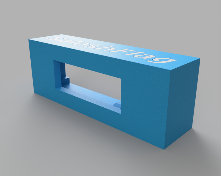
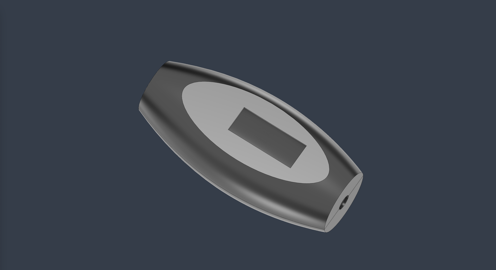
A traditional baton and its eventual technological replacement.

This post outlines the challenges I encountered and the steps I took to turn this idea into reality.

Cramming in All the Parts

From the outset I knew this would be a challenge to build because I would have to fit a lot of components into a small footprint:

  • Input(s) to set the tempo.
  • A way to display the selected tempo.
  • Some type of motor to vibrate the baton handle.
  • A button(?) to turn the device on/off.
  • A chip to run the code and connect all the components.
  • A rechargeable battery, and USB-C plug for charging.

After ordering a variety of components to play around with and seeing what felt best, I settled on: - A rotary encoder with push switch to handle dialing in the tempo and turning the device on/off. - An OLED display for showing the tempo. - A LiPo battery and prebuilt USB-C LiPo charging board. - An ATtiny84 to run the show.

Coding Blind: When Agents Can't See the Hardware

While I regularly use Claude Code for developing websites and python scripts, this was the first project I'd use it to write, compile, and flash the code onto a microcontroller. My setup didn't let me debug directly on the microcontroller, so the coding agent never knew whether its changes worked.

Normally when I use a coding agent to help me, I instruct it what the expected outcome should be and it can keep throwing metaphorical spaghetti against the wall until it sees what sticks (because it knows what the definition of success is). In this scenario, it would develop the code and then I would have to physically push some buttons on the hardware to test whether the code worked or not. I was part of the feedback loop back to Claude Code, updating it with what behaviors were happening on the physical device. This was a slow process, taking up to 30 seconds to write code, flash it, and test whether the changes were working.

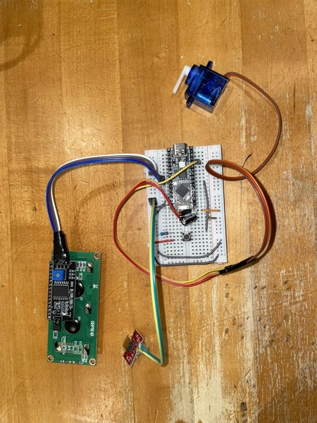
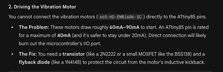
Another challenge with this project was that even though the code running on the ATtiny is simple, getting Claude Code to correctly understand how the various hardware components were wired together was a nightmare.

Initially I tried providing data sheets to Claude so it could understand the pinouts of each part. That didn't work great, so eventually I used that information to populate the CLAUDE.md file with both component pinouts and how they were all wired to each other. I didn't keep track of exactly how many times I was burned by Claude hallucinating an incorrect connection between component pins, but it was frequent enough to be frustrating.

Trying to get this information as clear as possible in CLAUDE.md eventually helped, but it still was not perfect. Every time Claude modified the code, I had to check that the working pin numbers stayed put.

First Time Trusting a $5 PCB

Breadboard prototype 
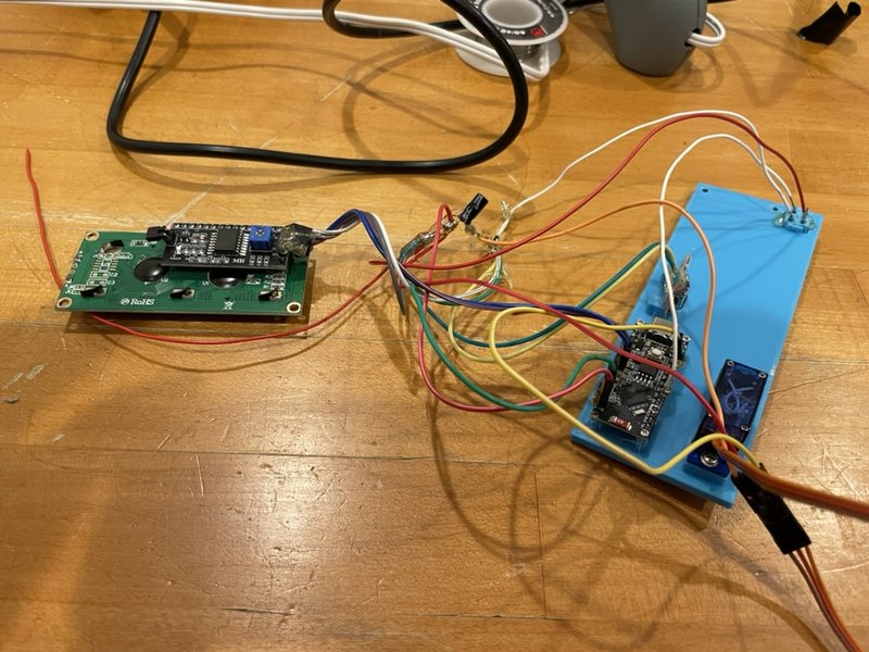
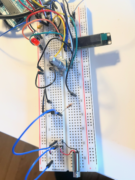
Breadboard prototype.

With the breadboard working, I started packing everything into the smallest footprint I could. I've never used custom PCBs (sometimes to my detriment), but for this project I thought it would be necessary in order to cut down on the bulk of wires between the components.

I chose KiCad for developing the board, since it seemed popular and capable of doing everything I needed it to do. This video on YouTube by HTM Workshop was amazing at walking me through the whole process from drawing the schematic to submitting the order to the PCB manufacturer. The KiCad schematic 
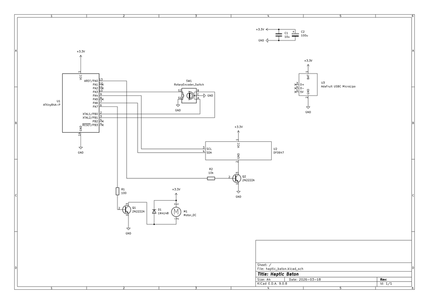
The schematic in KiCad.

The first thing I needed to create was the schematic. Picking components and wiring them was straightforward, including creating custom components that weren't in the KiCad built-in library. Once I completed the schematic, I printed it out and had my 8-year-old son build it on breadboard to ensure the schematic was accurate. He had fun building a "real circuit," and I got a free QA tester to double check my work.

3d render of the board from KiCad 
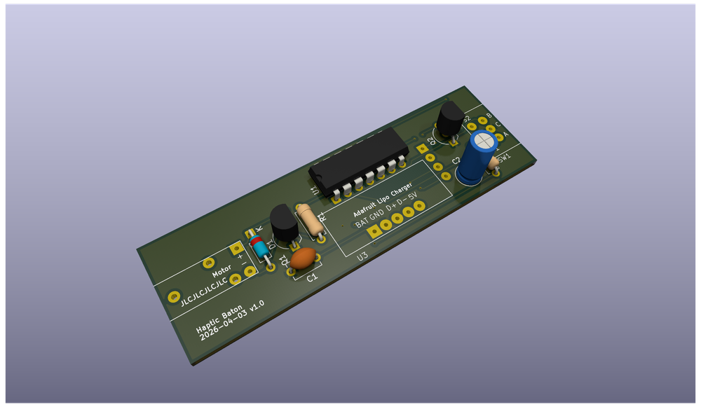
3d render of the board from KiCad.

With the schematic complete, I then had to select the packaging of parts for my circuit. I chose all through-hole parts (because that's what I had available from breadboarding the design), and it was at this stage I realized the final device would probably be too bulky. I pressed ahead anyway, figuring I should reserve judgement until I held an assembled board.

After labelling the components on the board for easier assembly, I sent the design to JLCPCB and a couple of weeks later the custom-made PCBs arrived in the mail: Manufactured PCB 
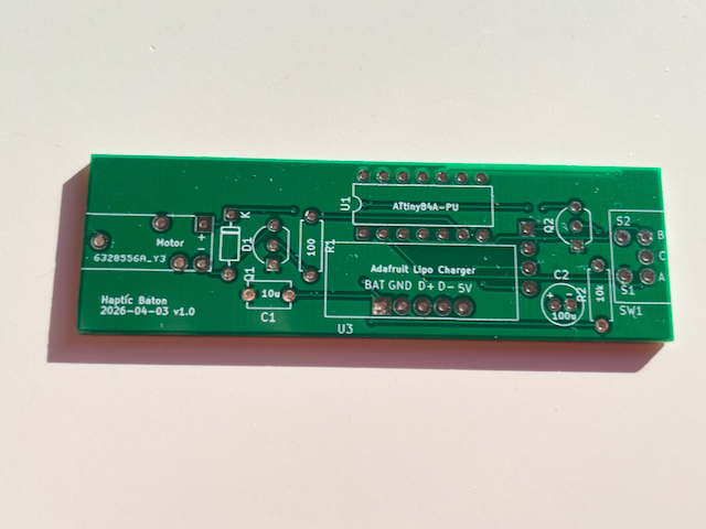
Look at all those connections I don't need to run wires between.

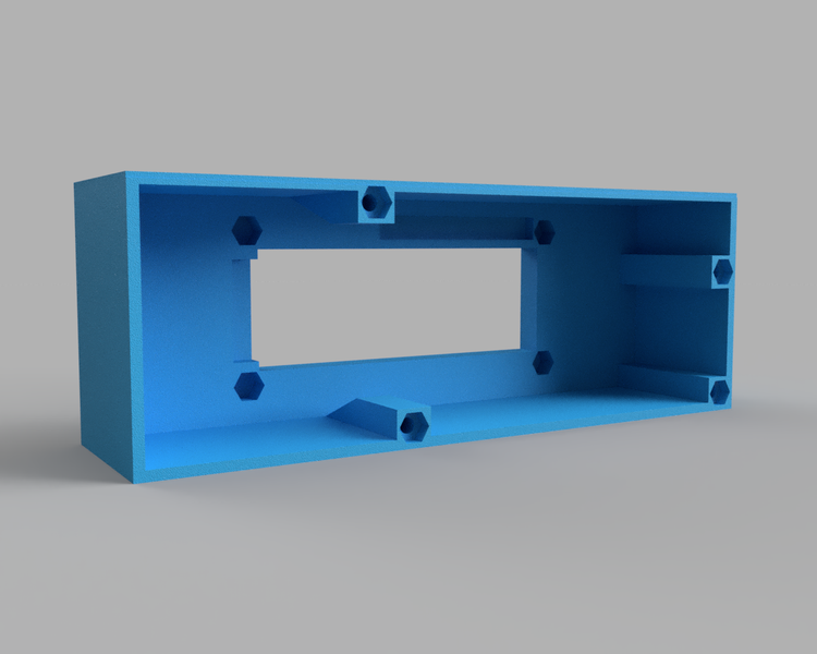
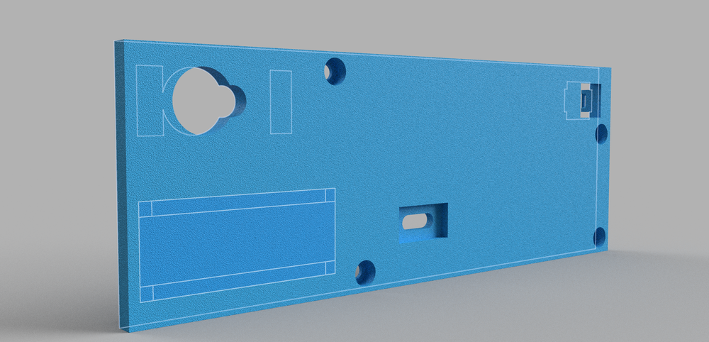
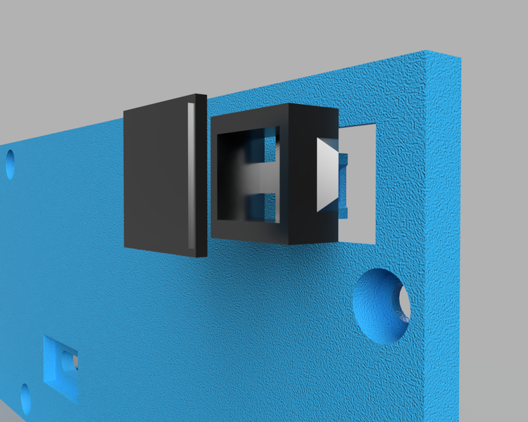
Assembling, Printing, and Rethinking

Front of the device displaying the tempo 
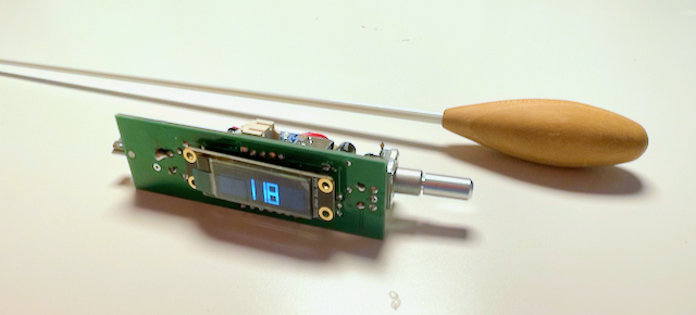
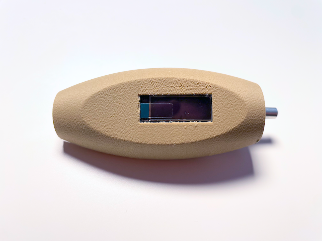
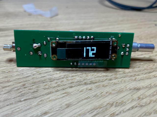
Front of the device displaying the tempo.

Back of the device with everything crammed in 
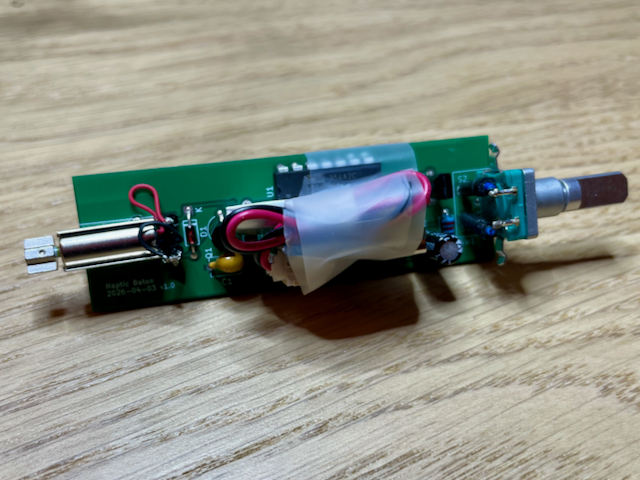
Back of the device with everything crammed in. The tape is temporarily holding down the battery.

Soldering the components to the PCB was easy (for $5 shipped, I think this is worth doing for all of my future projects) and soon I had a working device.

Watch this video on YouTube

The last step was to 3d print a handle enclosure. I struggled to get the design I wanted in Fusion 360 because I only have experience modeling boxes. For the handle to be comfortable to hold, it would need to be a little bit more organic:

A case that doubles as the handle Trying to design something that will be comfortable to hold and 3d print well.

Eventually I got an acceptable version and printed it:

3d printed case handle I didn't bother cleaning up this print since it was throwaway, but it confirmed that the printing quality would be good enough for what I wanted.

I knew this design would be too large for most hands, so I didn't finish fully modeling it. I did want to test the new wood PLA I bought for this project however, so I still printed the unfinished model to test its ability to be sanded smooth (it took to sanding well).

Things to Change in V2

While this first version is functional, it still needs to be smaller. To achieve this, I want the next iteration to include the following improvements:

  • Integrate the open source Adafruit LiPo battery charging circuit directly onto my PCB to save space.
  • Use SMD components where I can to save space.
  • Maybe look into a linear resonant actuator instead of a pager motor. This might end up being easier to fit into the enclosure than the motor.
  • Add mounting holes to the PCB. I thought I could 3d model a perfect fit, but quickly realized this is a giant pain. It's way easier to model some screw posts and mount the board to those.
  • Plan to attach the vibrating motor and encoder dial to the enclosure instead of mounting them directly to the PCB.

Overall I'm thrilled with how this initial version came out and I'm excited to begin working on the next version.

An LLM Saved My ATtiny85 From Certain Death

I almost ordered parts for a circuit that would have destroyed itself the instant I powered it on.

Instead, an LLM caught the critical flaw in my design, saving me time and money.

While I regularly see value in using LLMs in my coding projects, this is the first time I have seen real-world benefits when applying it to a hardware project.

Challenges with Electronics Components Shopping

I struggle with choosing electrical components from online catalogs. Knowing exactly which one of the 59,301 resistors I need for my project is always confusing:

Screenshot of hte Mouser website, showing the 59,301 wirewound through hole resistors I can buy for my project

In theory I understand most of the individual variables that can help me filter down my selection, but in practice I find doing this for all the parts in a project to be overwhelming. Ensuring each component will work correctly with the others, as well as substituting parts when they are out of stock or don't match the exact specs I need, is exhausting.

Fortunately, most of the parts I deal with are pretty inexpensive, so I often will buy several similar parts and then just try them in my circuit one by one, seeing which ones go up in smoke and which ones don't. As a hobbyist, this is more fun for me than spending hours reading datasheets.

However, this process breaks down when I completely mis-spec a component or outright forget to include one in my initial order. In those cases, I end up having to make a second order, often paying more for shipping than the cost of the additional components. It also means I have to wait another week for delivery (or longer if I'm ordering from China) before I can continue working on my project.

My Mistake

Not knowing what you don't know is one of the hardest problems to solve.

For my project, I need to be able to turn a motor on and off with a microcontroller.

Checking the datasheet for the ATtiny85 I am using in my project, I see that it allows for a maximum current of 40mA per I/O pin:

Datasheet for hte ATtiny85

The motor I'm wiring on the other hand pulls 75mA with a startup current of 105mA:

Datasheet for the motor showing higher current draw than the microcontroller can support

I missed these details when adding components to my cart because, as I mentioned before, my eyes were going blurry from comparing all these different components and datasheets.

If wiring the motor to the microcontroller wouldn't fry it instantly, it would certainly shorten the lifespan of the microcontroller.

LLMs as a Second Set of Eyes

Fortunately, before I clicked the "Buy" button, I decided to copy and paste my cart of components into ChatGPT, Claude, and Gemini to see if they could identify any errors:

Gemini telling me I forgot a transistor All three LLMs caught the error, but Gemini had the cleanest output.

I made a mistake and Gemini reminded me, saving me a few bucks and a week of waiting for more components to be delivered.

Conclusion

Do I trust everything LLMs output? No. I've used them enough in software projects to know when they are wrong or output something differently from how I want to build it.

However, as a novice in electronics, I found the LLM to be extremely helpful in double checking my circuit design work.

Hopefully I learn through this experience and have better luck in the future, but from now on I'll always run my cart of parts through the LLM to double check my selections.

SplashFlag - Building an IoT Swimming Notification Device from Scratch

The SplashFlag Notification Device

After setting up dozens of Internet of Things (IoT) smart home devices, I started to wonder: how hard could it be to build one from scratch?

I needed a project to learn on, so I decided to create something fun: a device that alerts my neighbors when my kids go swimming, extending the invitation for their kids to come swim too.

What follows are the lessons I learned from building such an IoT device from scratch.

Demo and Code

Here's a short video demoing the device and its features:

Watch this video on YouTube

The instructions and code for building your own Splashflag can be found at the bottom of this post, otherwise keep reading to learn about my journey in building the device.

Why SplashFlag?

How many times can you play Marco Polo in a pool with an adult and two kids? I know that my kids far prefer the company of their friends who have a lot more energy.

Originally our idea was to put up a special "we're swimming" flag outside in our front yard when our kids were in the pool, alerting the neighbors that they are welcome to come over and swim as well. The flag would be an open invitation, without the overhead of planning, group texts, and phone calls.

I quickly realized this idea wouldn't work because: 1) The flag wouldn't be easily visible from every neighbor's house 2) By the time people saw the flag and came over, we might already be wrapping up our swimming session

What I needed to solve this social problem was technology (or rather, I needed an excuse for a new technology hobby project), which is how the idea for SplashFlag was born.

Key Features and Learnings

This wasn't my first time building an embedded device, but it was the first time I tried to follow at least some semblance of best practices: main loops less than a thousand lines long, no hardcoded passwords, etc...

If this was going to be a true learning project, I wanted to be more organized: use classes, design hardware and software that could handle errors gracefully, and create a way for users to connect the device to their WiFi without me ever needing to know their credentials.

While I wouldn't consider this code to be perfect (or even necessarily "good"), it's a huge improvement over hardware projects I've built in the past, so I consider it a success.

Below is an overview of the major features I built into the device.

Servo Flag

The servo and plastic flag

This is how the idea started: instead of the physical flag in my front yard, it would be a small plastic flag sitting on the counter in a friend's home.

Whenever the device receives a message, the flag goes up until the message expires. Besides being a fun feature, it works well in households where the kids are still too young to read the details of the message - regardless of what the screen says, if the flag is raised, they know the Wagners are swimming and they're welcome to come swim too.

Clear/Reset Button

Reset Button

This button wasn't originally planned as a feature. The first time I got the servo flag working and realized it might be raised for an hour, I knew that as a parent I'd want a way to clear the notification without my kid seeing it. So the hidden button on the back of the device became a necessary enhancement. Push it, and the message clears while the flag goes down.

It also serves double duty for triggering a factory reset.

LCD

In addition to the servo flag, the LCD displays messages about swimming. The default message indicates how long we plan to swim, but the web app (see below) lets me write any message, so something like "feel free to stay for pizza" is a potential customization.

The LCD also displays system messages, like when the device is having trouble connecting to WiFi or when the messaging server is down.

The code for the LCD was fun to write: since the screen can only fit two rows of 16 characters, I had to write a function that could split any length message so it fit these constraints and scroll across multiple screens.

This is also where I first encountered overflow errors and needed to add max-length validations: Memory overflows displaying garbled characters on the LCD screen

The screen works well and serves its purpose, but along with the I2C adapter, it is easily the biggest component in the device. Next time, I plan to look for slimmer options, because the device size (especially the front frame with the LCD) could have been considerably smaller if I had chosen a different board.

Captive Portal

Screenshot of the Captive Portal

Before this project, I never knew the magic that allowed login pages to pop up on your device when connecting to a guest wifi network.

It turns out, it's DNS!

This guest wifi login experience is what I wanted to build into my device. After all, I wanted my neighbors to be able to set this up in their house, all on their own, without me needing to know or hardcode any WiFi passwords.

The short explanation of how this works is that when your phone connects to a new WiFi network, the phone will try to visit certain well-known URLs. If you own the WiFi network, you can configure DNS to look for those standard URLs and intercept them, serving your own login page.

Fortunately there are some good libraries for setting up a DNS server on ESP32s and intercepting traffic, then serving your own captive portal where people can input their WiFi credentials.

Over the Air (OTA) Updates

Another feature I wanted to include was the ability to update the firmware remotely. Debugging and flashing new firmware while the device was sitting on my desk was easy, but I know my code isn't perfect so I wanted a way to update these devices remotely in the future.

Fortunately the ESP32-S3 Nano device I was using allows for OTA firmware updates. I set up the library for this and have it check the GitHub releases page for SplashFlag every day to see if a new version is available. If a new version exists, it will download the update and install it.

Here's hoping I don't accidentally brick anyones SplashFlag device.

Web App

SplashFlag web app

I wanted a simple interface for sending messages to all devices, so I created a single page web application. It defaults to the most common message I would send, with input parameters to adjust the duration of how long the message is displayed on the devices.

The website runs on my home server and I expose it through CloudFlare Tunnels so I can easily access it from my phone (or anywhere). I also added HTTP Basic Authentication to the website - not the most robust option, but good enough for this project. In the future, if I upgrade anything, it would be the authentication system. Basic Authentication is secure enough, but it doesn't play nicely with 1Password or Safari on iOS, which causes some minor annoyances.

The web app sends a message to the MQTT broker (see below) over WebSockets, which then publishes it to all devices. Because this is just a simple API call, I could easily program a smart button to trigger this in the future, allowing my kids to send the notification themselves when we head out to the pool.

MQTT Messaging

I didn't want my devices long-polling a web server to check the status of new swim messages. Instead I decided to use an MQTT broker running in my home lab to transmit messages to the SplashFlag devices running the MQTT client code.

I am using mosquitto as the MQTT broker. The MQTT broker service runs on my home server and is exposed via WebSockets to the web app. All of the devices subscribe to the broker service, so whenever a message is published, every device receives the message and updates its screen and raises its flag.

Debugging Hardware Flag

Since I may need to continue development (e.g. fixing bugs) once these devices are in the wild, I wanted a way to send messages to only my debugging device. Fortunately, ESP32-S3 Nanos have a unique mac address identifier, so I wrote code to check whether a device is a development unit under my control. If it is, it subscribes to an additional MQTT topic that only receives debugging messages. Debugging messages are set through the web app via a toggle: Debug mode toggle

Debug mode message displayed on the device

The fact that the ESP32-S3 Nanos have their own unique identifier means I don't need different code for production devices versus debugging devices (or at least in that section of the code). While I could have handled this in other ways, I'm satisfied with how this solution works.

3D Printed Case

While I learned a ton designing this case, the smartest thing I did was test print each CAD feature as I finished designing it. This meant printing something like the servo holder only took 15 minutes, and then I could dry fit the parts together to ensure they actually fit. This saved a lot of time on iterating fit and printing, as well as minimizing plastic waste. SplashFlag device

My CAD design experience before SplashFlag was limited to simple enclosures. SplashFlag taught me how to make more complex designs, including screw mounts and snap-fit parts.

The case design is simple. The front panel holds the LCD. The remaining components (ESP32-S3 Nano, servo, USB-C power plug, tactile reset button) mount to the back panel. CAD design of the front panel

CAD design of the front panel from the back

As mentioned earlier, the LCD with I2C breakout took up a lot of room, leading to the wide frame around the LCD.

The ESP32-S3 Nano, servo, and USB-C plug attach to the case with small metric screws. The LCD panel bolts onto the front plate with an embedded nut. Backpanel render

While I was designing this, it took many iterations to figure out how to get all the parts to fit together while minimizing space. I also had to consider the limitations of 3D printers and assembly so the final case would be possible to print and assemble successfully.

One oversight I made was forgetting to leave space for the bolts that would hold the two halves of the case together. Originally I was going to make the case snap-fit together without any hardware, so I didn't include bolts in my design, but I decided to add bolts once I realized how relatively heavy all the components would be and all the wiring that would need to stay confined to the inside of the device. If I had modeled the case properly in Fusion360 with components, I could have easily moved things around after I realized I needed case bolts. But since I didn't realize I could do that until I had spent hours designing the case the wrong way, I decided to be OK settling with the imperfections. Case bolts as an afterthought

My favorite part of the case is the snap-fit housing for the tactile button. It allows for a small breadboard switch to become a neatly integrated button. Definitely a design I will use again in future projects: Exploded view of button

the final back button

As a final embellishment, I added the text SplashFlag to the top of the device. I only have a single-color 3D printer, so this meant printing the outline of the letters in blue, then the letters themselves (slightly smaller) in white. Final assembly involved super gluing them together on the top of the case.

What Isn't Included

As much as I packed this device with features, I didn't include everything.

If I wanted to devote more time to this project, I'd probably first enable TLS for all HTTP connections. The idea of writing code to automatically update the CA certs on the device (and maintaining TLS certs on the server app) over time didn't seem worth it for a hobby project.

Also, secrets like the WiFi password and MQTT credentials are not encrypted at rest. They are stored in the ESP32-S3 Nano's non-volatile memory, allowing anyone with physical access to the device to potentially retrieve them without too much effort. The ESP32-S3 Nano does have eFuses which can help with storing cryptographic keys (which could then be used to encrypt the credentials), but adding that capability didn't make the cut due to time constraints.

Conclusion

Who knows if I will use it, but this build taught me I am capable of making steady, regular progress towards long-term projects.

I am probably not going to large scale manufacture these for the neighborhood, but I gained confidence in building a complete hardware device on my own that works well. When the next product idea strikes, I'll already have a lot of the knowledge (and code!) required for building it.

Is it perfect? No. Is it better than some IoT devices I've purchased, with easier updates and repairs? Definitely.

How to Build Your Own SplashFlag

Parts List

  • ESP32-S3 Nano
  • 1602 LCD Display with I2C adapter for easier wiring
  • Feetech FS90 9g Servo
  • 6x6x5mm tactile push button switch
  • .1 uF decoupling capacitor
  • 220ohm pull-down resistor
  • USB-C Power Adapter and cable
  • Variety of M1.6-M2.5 screws and bolts to mount all the components

Code and Files

Complete code for the ESP32-S3 Nano and web app, as well as the 3D printed case are available at the SplashFlag GitHub Repo.

The code for the ESP32-S3 Nano is configured with PlatformIO. This configuration handles downloading and installing all C++ dependencies. If you use PlatformIO in Visual Studio Code like I do, you can open the repo's hardware folder, build the code, and upload it to the board.

The web app runs in a Docker container. You will need to generate an auth password for the mosquitto service as well as configure a Cloudflare Tunnel if you are going to be self hosting. Details for doing this are in SplashFlag backend README.

Case Assembly and Wiring

3D printing the files shouldn't require any supports, with the exception of the cutout for the USB-C cable. I used .10mm layer heights with PLA+ filaments. The snap-fit tactile button is the component with the tightest dimensional tolerance - I recommend slicing up the back panel and printing only this button enclosure at first to ensure your printer is calibrated correctly. If that piece prints correctly, the rest of the case should print without any issues.

I don't have a nice wiring schematic, but the photo below with details should help.
- The I2C adapter is wired to pins A4 and A5. - The servo is wired to D9 as well as 5V and ground. I put the decoupling capacitor near the servo to ensure smooth power. - The USB-C adapter gets the stable power in, and it is tied to the VIN and ground pins on the ESP32-S3 Nano. - The tactile button is tied to ground with the pull-down resistor and wired to D4 on the ESP32-S3 Nano. Components wired together via a breadboard

After confirming everything worked on a breadboard, I mounted the components to the case. I then soldered the component wires together, tested again, and once I was confident things still worked, encased all connections in hot glue: Wires all hooked up internally for the case

Note: the red wire hanging off to the left in the above photo was an extra wire I later clipped off - I miscounted while creating my wires.

Maybe my next project will involve designing a custom PCB board to make the wiring easier.